Phendrana Assembly
Click Here for main Phendrana pageParts Needed
- Choc V1 Keyswitches
- Any Choc V1 Low Profile switch should fit
- 85 Switches needed, recommended to buy 90
- Choc Keycaps
- Other keycap sets work, but this keyboard is specifically designed for this set. Other sets or individual keys will create gaps between keys
- Choc Stabilizers
- 6x 2U Stabilizers needed, recommended to get the "8 sets"
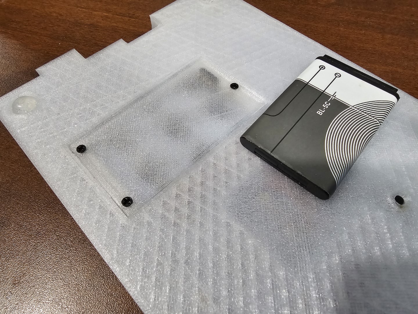
- BL-5C Battery
- Ensure the size is over 1000mAh
Assembly Instructions:
Partial instructions for Phendrana are below, however complete instructions to build from scratch are unavailable.
Assembly instructions:
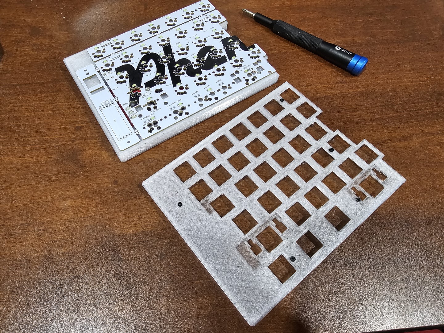
- Unscrew top plate
- There should be 5 screws on the left, and 6 on the right
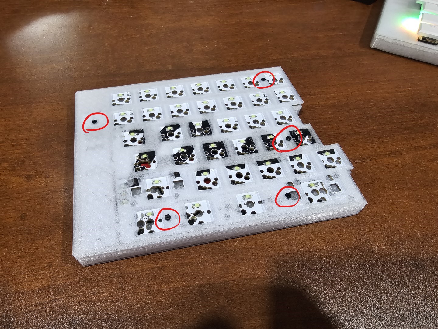
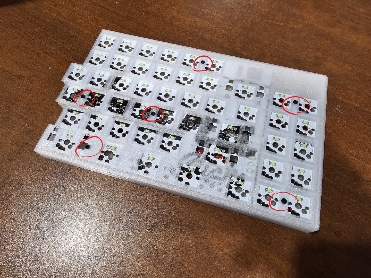
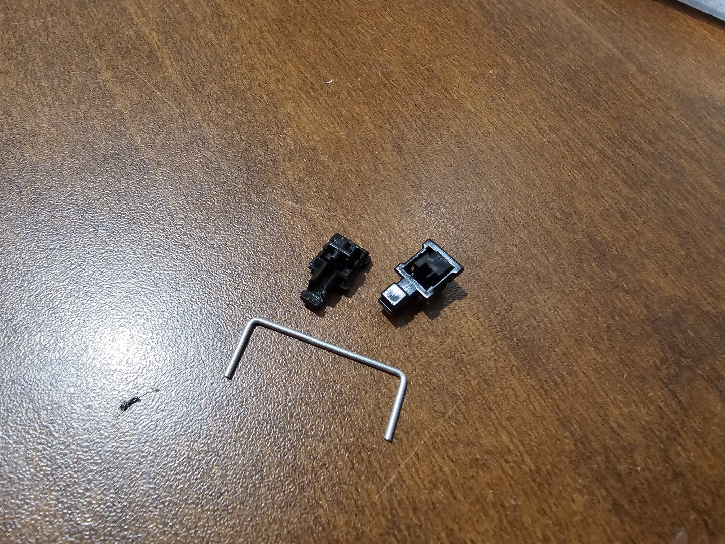
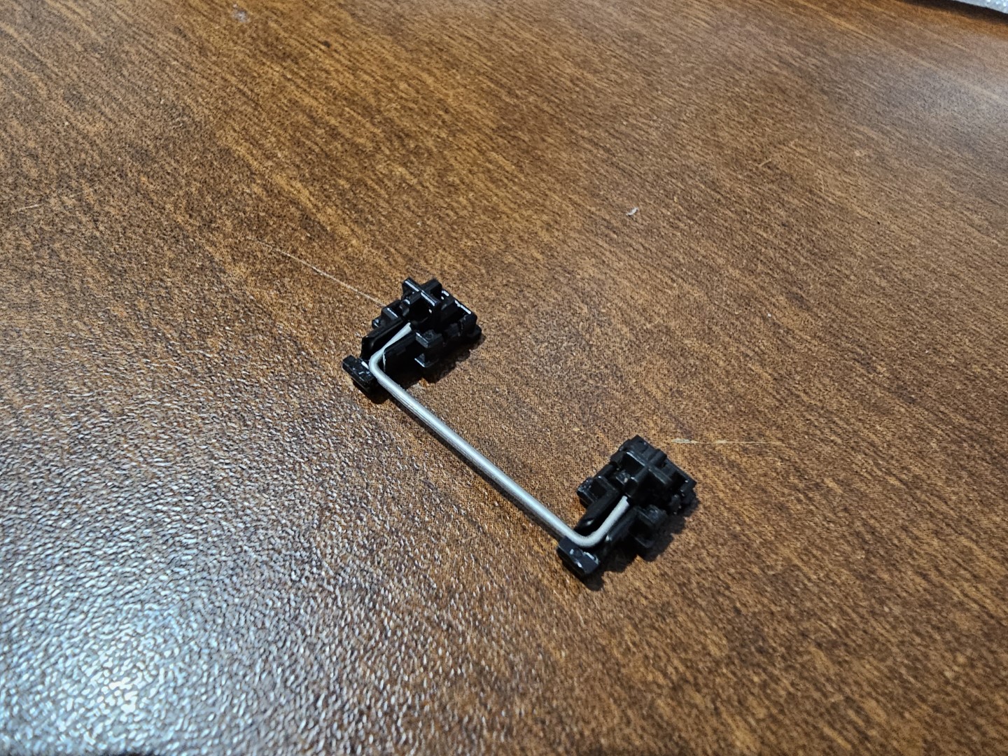
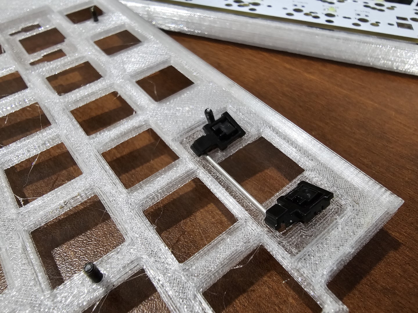
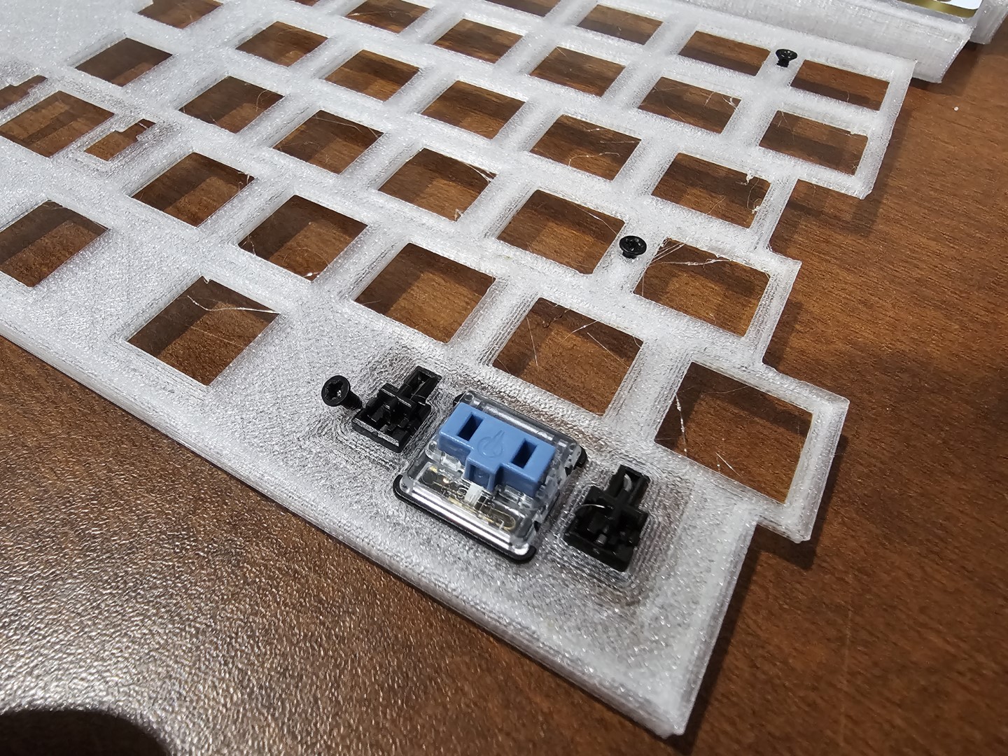
- Attach stabilizers to Plate
- Be careful installing these, the plate is very thin, so they may easily break
- It is recommended to install the stabilizers one side at a time. Preferably install the switch side first, then push in the other side (see third photo)
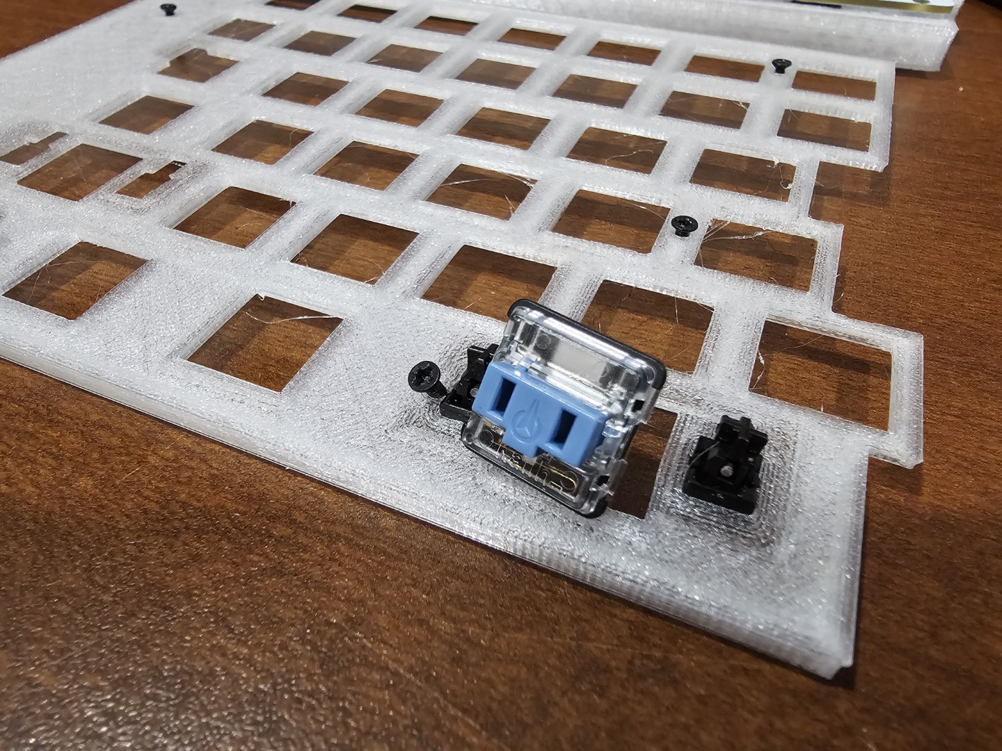
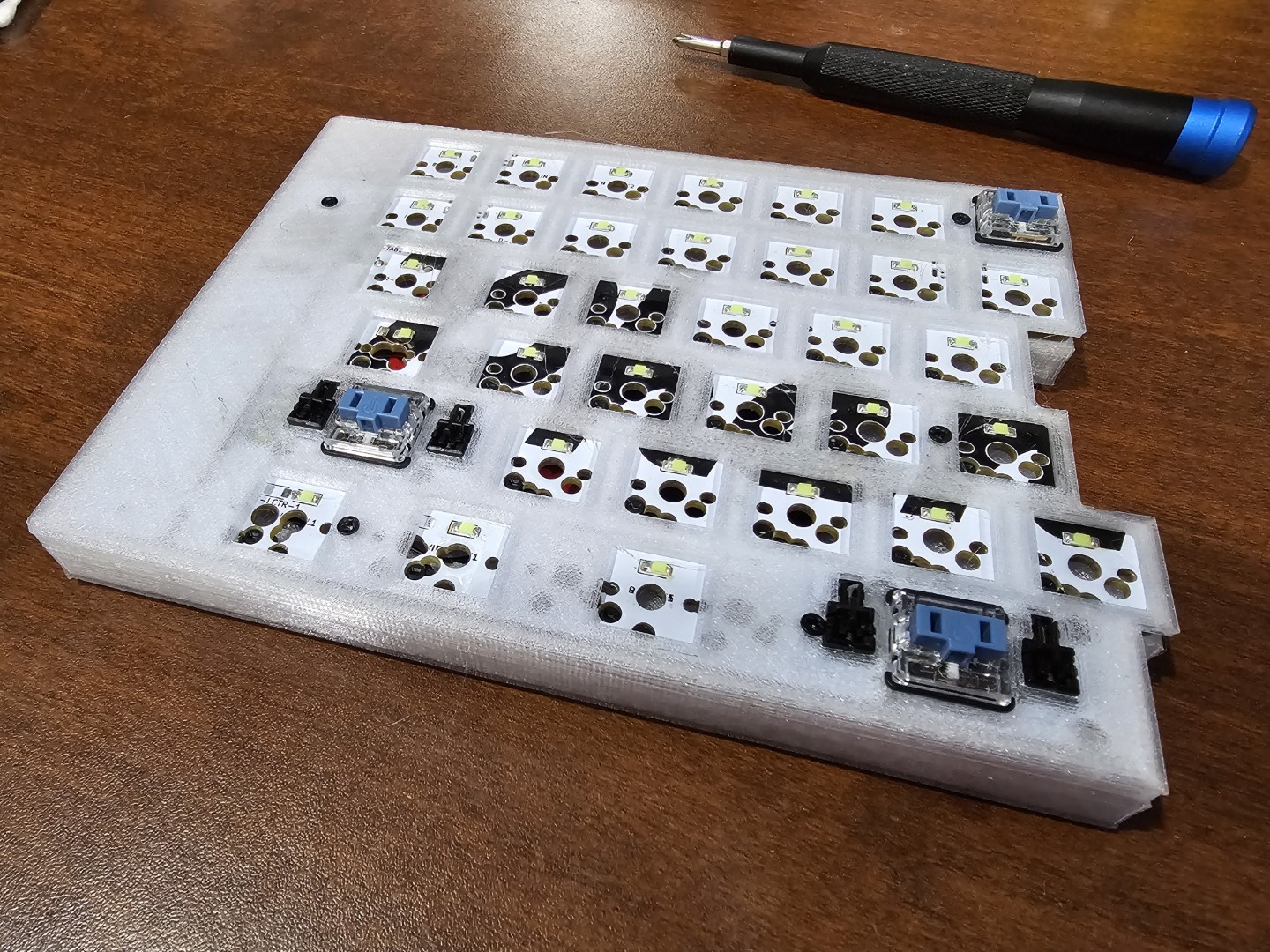
- Attach some switches to the plate, and attach those switches into the PCB
- It is recommended to attach around the stabilizers, to keep them in place
- It is also recommended to test with a keycap, to ensure that the stabilizers don't bind
- If stabilizers do bind, make sure the switch, and two sides of the stabilizer are sitting flat against the plate
- Screw the Plate back into the bottom case
- The screws shouldn't need to be very tight, however make sure the screws around the stabilizers are looser, otherwise the stabilizers may bind when typing
- Attach all other switches into the PCB/Plate
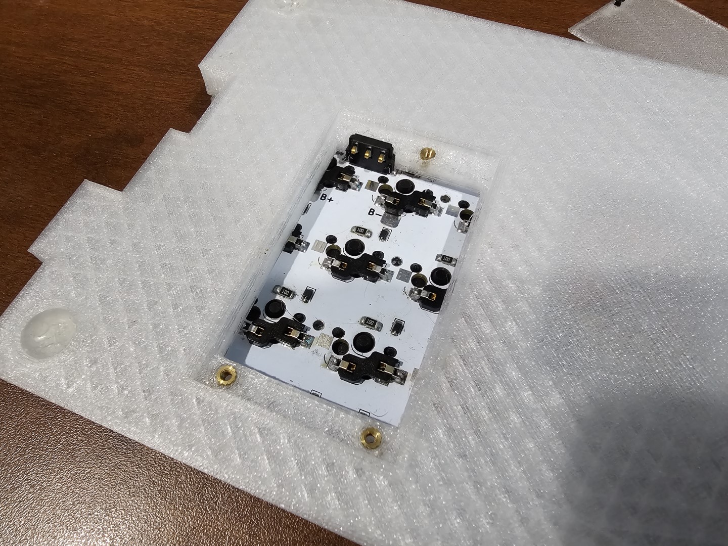
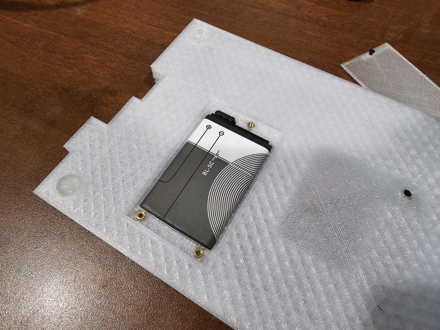
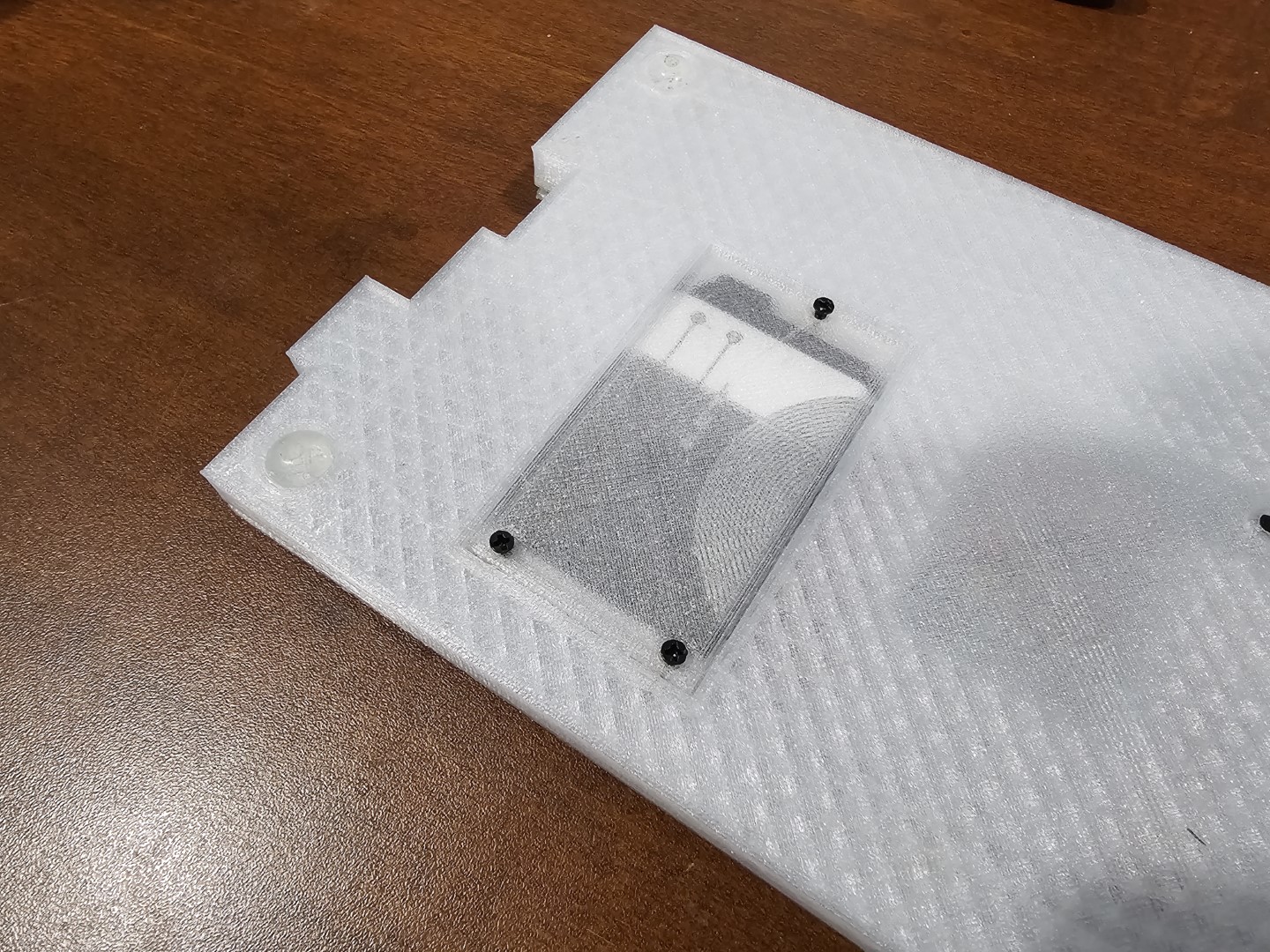
- Unscrew back battery cutout
- Place in battery
- Note: The battery should only go in one way, the leftmost pin is V+, and the rightmost is V- (GND)
- Battery should be at least 1000mAh, it is designed to charge at 1000mA. Any smaller battery may be damaged if used
- Attach keycaps to switches
Notes:
- If any service is required - remove the battery first
- If the battery is not removed while the PCB is taken out, it has a chance of ripping off the battery connector from the Keyboard
Please note the default key layer is: